
how to wire the terminal block
author: Clark
2026-04-01
How to wire a terminal block | An Industrial Standards
In alignment with national electrical construction codes and universal IEC international guidelines—particularly within photovoltaic energy storage, industrial control distribution, inverter systems, and high-current BMS applications—the wiring craftsmanship applied to terminal blocks directly dictates circuit safety, conductive stability, and project compliance for final acceptance. The industry has long established clear, tiered requirements for wiring: thin wires and low-voltage signal lines may be connected directly (provided they are properly prepared), whereas thick cables, multi-strand flexible wires, and high-current circuits *must* utilize crimped copper lugs as an intermediary; connecting bare wires directly into the terminal block is strictly prohibited. From a professional yet accessible perspective, this article aims to standardize the wiring process and clarify the boundaries of regulatory compliance.
I. Wiring Classification: Strict Industry Distinctions
Electrical wiring is strictly categorized into two distinct classes, and the procedures for each must not be intermingled:
Category 1: Single-strand solid wires under 10mm², low-voltage signal lines, and thin control wires. These are typically used with PCB terminals, small screw terminals, and low-voltage signal circuits. Once properly prepared (e.g., stripped to the correct length), these wires may be inserted directly into the terminal block without the need for copper lugs.
Category 2:Multi-strand flexible copper wires of 10mm² or larger, main power cables, main circuits within energy storage cabinets, and high-power incoming lines. In accordance with engineering acceptance standards, inserting bare wires directly into the terminal block is prohibited; instead, a copper lug of the appropriate specification *must* be crimped onto the wire to form a solid termination before connecting it to the terminal block.
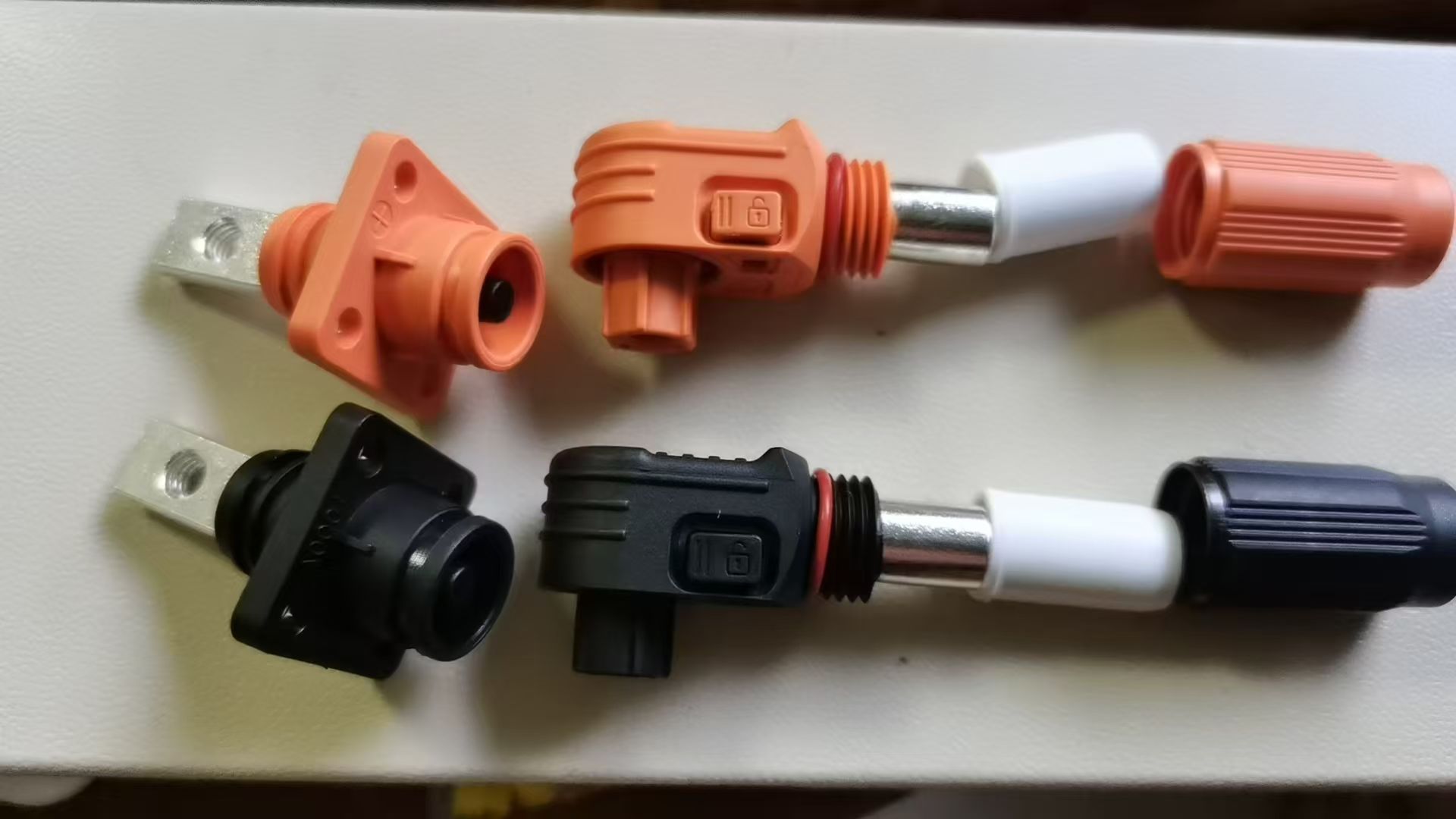
The Core Rationale: When multi-strand flexible wires are clamped directly, individual strands are prone to splaying out, leading to loose connections or "virtual contacts" (poor electrical contact) that can easily loosen further under vibration. Under high-current loads, such poor connections can rapidly generate heat and cause electrical arcing. Conversely, crimping a copper lug consolidates the loose strands into a single, rigid terminal unit; this significantly increases the contact surface area and reduces contact resistance, thereby satisfying the rigorous requirements for long-term, high-load operational reliability.
II. Standard Wiring Procedure for Low-Voltage Fine Wires
Step 1: Power Disconnection and Verification. Cut off power and verify the circuit is de-energized; clean wire ends to remove oil, grease, or oxidation layers.
Step 2: Precise Insulation Stripping. Strip 5 to 8 millimeters of insulation precisely without damaging the internal copper core; for multi-strand fine wires, manually twist and bundle the strands tightly to prevent any fine filaments from fraying or protruding.
Step 3: Terminal Screw Preparation. Loosen the terminal screw to create space for wire insertion, but do not completely remove the screw.
Step 4: Wire Insertion. Fully insert the neatly bundled copper core into the bottom of the terminal hole, ensuring full and flush contact between the wire and the terminal.
Step 5: Torque Tightening. Tighten the screw using the specified standard torque; gently pull on the wire to verify that it is securely fastened and not loose.
Step 6: Pre-Power Verification. Before applying power, use a multimeter to check for continuity and verify that there are no hidden hazards such as short circuits or loose connections.
This procedure is applicable to wiring for circuit board signals, low-voltage control lines, and small-scale industrial control terminals.
III. Compliant Wiring Procedure for High-Current Cables + Copper Lugs
Step 1: Specification Matching. Strictly select the appropriate copper lug based on the cross-sectional area of the cable; for high-humidity or outdoor environments, select tin-plated, anti-oxidation copper lugs, and strictly avoid using non-standard, thin-walled copper connectors.
Step 2: Cable Pre-treatment. Strip the cable insulation precisely so that the exposed copper core length matches the depth of the copper tube within the lug; use sandpaper to polish and remove any oxidation layers, ensuring the conductive contact surface is clean.
Step 3: Standard Crimping. Use a specialized hydraulic crimping tool with the corresponding die to perform a centered, multi-point crimp; the resulting crimp should be full, free of cracks, and free of deformation—strictly avoid using ordinary pliers for makeshift crimping.
Step 4: Insulation Protection. Cover the crimped area with heat-resistant heat-shrink tubing; use a heat gun to apply heat evenly, causing the tubing to shrink and seal the connection. For outdoor applications, add an additional layer of waterproof insulation wrapping.
Step 5: Terminal Connection. Position the crimped copper lug against the conductive surface of the terminal, ensuring it is aligned squarely and without tilting.
Step 6: Torque Tightening. Use a torque wrench to tighten the connection to the specified standard torque value, thereby preventing issues caused by being too loose (leading to overheating) or too tight (leading to stripped threads or cracked terminal housings).
Step 7: Temperature Rise Verification. After operating under full load, measure the temperature of the connection point; the temperature rise at the joint must be maintained within the safe limits established by industry standards.
IV. Strictly Prohibited Wiring Practices
1. **Direct termination of bare, heavy-gauge cables:** This practice creates a high risk of arcing and terminal burn-out.
2. **Mismatch between cable lugs and cable specifications:** Using undersized lugs for heavy-gauge cables results in improper crimping and creates latent safety hazards.
3. **Omission of crimp protection:** For outdoor applications, the lack of protective measures leads to oxidation and corrosion over time, eventually resulting in poor electrical contact.
4. **Manual screw tightening without torque control:** Relying solely on tactile feel rather than controlled torque settings allows wiring connections to loosen over time due to vibration.
The aforementioned improper practices are key inspection points during the acceptance phase of photovoltaic and energy storage projects, both domestically and internationally.
The aforementioned improper practices are key inspection points during the acceptance phase of photovoltaic and energy storage projects, both domestically and internationally.
V. Compliant Matching: Professional Terminals for Standardized Wiring
The entire range of Telian wiring terminals strictly adheres to national standards and IEC wiring specifications. Featuring high-conductivity copper materials combined with reinforced thread structures, these terminals are designed for seamless compatibility with standard cable lugs. They offer low contact resistance as well as high resistance to vibration and temperature fluctuations. Furthermore, Telian provides comprehensive, end-to-end selection support to assist various new energy and industrial automation projects in achieving fully compliant wiring and ensuring stable, reliable operation.
Terminal Blocks Evolving as Critical Connectors
How to Use a Terminal Blocks
Related Article
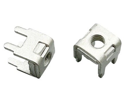
In industrial electrical systems, battery storage, and automotive wiring, connector terminal pins are the unsung backbone of power and signal transmission.
how to remove connector terminal pins
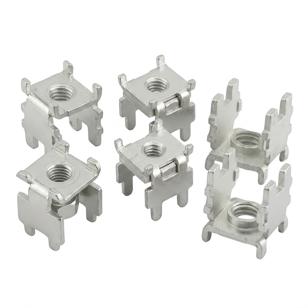
olar and energy storage inverters are the core equipment of the new energy industry, responsible for converting DC power generated by photovoltaic panels and lithium battery packs into usable AC power.
The Indispensable Core Partner of Solar