how to remove connector terminal pins
How to Remove Connector Terminal Pins: A Data-Driven Technical Guide for Industrial Reliability
Table of Contents
- 1. Why Proper Terminal Pin Removal Is Critical for System Performance
- 2. Common Scenarios for Removing Connector Terminal Pins
- 3. Tool Selection: A Data-Driven Approach
- 4. Step-by-Step Terminal Pin Removal Procedure
- 5. Common Mistakes & Failure Mode Analysis
- 6. Built for Maintainability: Telian TLS54103 Screw Connector Terminal
- 7. Expert Tips for Long-Term Terminal Reliability
- Conclusion
- Contact Information
In industrial electrical systems, battery storage, and automotive wiring, connector terminal pins are the unsung backbone of power and signal transmission. Yet improper removal of these small components is a leading cause of connection failures, unplanned downtime, and safety hazards. Industry data shows that 32% of low-voltage and high-voltage electrical connection failures stem from mechanical damage during terminal pin removal or reinstallation. For 600V-class high-power applications, the failure rate jumps by 67% when standard operating procedures are not followed.
This guide breaks down the step-by-step process of removing connector terminal pins with data-backed best practices, common failure modes, and tool selection criteria. Whether you are performing field maintenance, prototype debugging, or terminal replacement, this technical framework will help you reduce damage rates, extend component lifespan, and maintain system integrity. We will also introduce a purpose-built screw terminal solution engineered for high durability and repeatable maintenance — the TLS54103 from Telian Electronics.


1. Why Proper Terminal Pin Removal Is Critical for System Performance
Removing terminal pins is not just a mechanical task — it directly impacts electrical performance, operational cost, and workplace safety. Cutting corners during extraction creates cascading failures that are often discovered only after costly downtime.

1.1 Electrical Reliability Impact
Terminal pins rely on precise mechanical contact to maintain stable conductivity. Even minor deformation of 0.1mm can increase contact resistance by 15% to 40%, leading to excessive heat generation, voltage drop, and signal loss. In high-current applications (50A+), a 20% rise in contact resistance can elevate junction temperatures by 15°C to 25°C, accelerating insulation aging and increasing fire risk.
For battery management systems (BMS) and energy storage terminals, poor contact from damaged pins is responsible for 28% of premature battery pack failures, according to 2025 energy storage industry maintenance reports. Over the lifespan of a 10-year BESS installation, terminal-related failures can reduce total energy throughput by an estimated 4.2%.
1.2 Financial & Operational Cost
Unplanned downtime caused by terminal failure carries a steep price tag. For industrial automation lines, the average cost of a single electrical connection failure ranges from $1,200 to $3,500 per hour, including lost production, labor, and replacement parts. In automotive manufacturing, terminal-related wiring defects account for 14% of all rework on vehicle assembly lines.
Proper removal procedures reduce terminal damage rates by up to 82%, according to IEC 60947-7-1 compliance studies, directly cutting maintenance costs and extending component service life. For facilities with 500+ terminal points, this translates to an estimated 35% reduction in annual electrical maintenance spend.
1.3 Safety Risks in High-Voltage Environments
In 600V and higher voltage systems, damaged terminal pins create two major safety hazards: exposed live parts and arc flash risk. When terminal pins are bent or misaligned during removal, the risk of insulation breakdown increases by 2.3 times. For workers performing live maintenance (not recommended), the probability of arc flash injury rises 12-fold when terminals are mishandled.
This is why selecting robust terminals and following strict removal protocols is non-negotiable for industrial, automotive, and energy storage applications.
2. Common Scenarios for Removing Connector Terminal Pins
Terminal pin removal occurs across the entire product lifecycle, from R&D to end-of-life decommissioning. Understanding the scenario helps you apply the right level of care:
- Field Maintenance & Repair: Approximately 18% of routine electrical maintenance tasks require terminal pin removal for inspection, cleaning, or replacement. For outdoor installations, this figure rises to 27% due to higher corrosion exposure.
- Prototype & Testing: During product development, engineers may remove and reinsert terminals 20–30 times per prototype iteration for design validation and compatibility testing.
- Wiring Harness Rework: In custom assembly, 25% of harness modifications involve pin extraction and repositioning to accommodate design changes.
- Failure Analysis & Troubleshooting: When diagnosing connection faults, technicians remove terminals to measure contact resistance, check plating integrity, and inspect lock mechanisms.
Across all scenarios, the core goal remains identical: remove the pin without damaging the terminal, housing, or adjacent components.
3. Tool Selection: A Data-Driven Approach
Using the wrong tool is the #1 cause of terminal damage during removal. Below are the required tools and their performance specifications, based on industry standards and field failure data.
3.1 Terminal Pin Extraction Tool
A dedicated extraction tool (also called a pin ejector or terminal release tool) is non-negotiable. For screw-type terminals and stamped terminals, the tool must:
- Have a tip hardness of HRC 58–62 to withstand repeated insertion without deformation
- Match the terminal’s internal latch geometry with a dimensional tolerance of ±0.03mm
- Support a minimum service life of 5,000 extraction cycles
Using a flathead screwdriver, paper clip, or other improvised tool increases housing damage rate to 72% and terminal pin bending rate to 58%, compared to 3% and 2% respectively with proper tools.
3.2 Auxiliary Tools
- Precision tweezers with tip tolerance of ±0.02mm for handling small pins
- Digital multimeter with ±0.1V accuracy for voltage verification before work
- Anti-static wrist strap (for sensitive electronic circuits)
- Insulated gloves rated for the system voltage (compliant with IEC 60903 for 600V+ applications)
- 10x magnification loupe for post-removal plating inspection
3.3 Pre-Work Safety Checklist
- Perform Lockout/Tagout (LOTO) on the main power supply
- Measure terminal voltage to confirm residual voltage is below 5V for high-voltage systems and below 24V for low-voltage systems
- For capacitive circuits, wait at least 3x the RC time constant to ensure full discharge
- Document terminal position and wiring orientation before removal to avoid reassembly errors
4. Step-by-Step Terminal Pin Removal Procedure
This procedure is optimized for screw-type PCB terminals and wire connector terminals, with quantitative thresholds for each step to ensure consistency and reduce human error.
4.1 Step 1: Power Isolation & Safety Confirmation
Before any disassembly:
- Cut off main power and apply LOTO locks to prevent accidental energization.
- Test each terminal with a calibrated multimeter. For DC systems, measure both positive and negative poles to ground.
- For energy storage systems, confirm BMS discharge completion and bus voltage below the safe threshold (typically <60V for touch-safe operation).
Data check: Never proceed if residual voltage exceeds 5V for high-voltage terminal work.
4.2 Step 2: Remove Connector Housing
Most terminal housings use side latches, top latches, or screw locking:
- Identify the latch type and apply uniform opening force. Typical latch release force is 15N–35N.
- If the latch feels stuck, do not pry with excessive force. Apply a small amount of silicone lubricant and wait 30 seconds.
- Lift the housing straight off to avoid scraping terminal pins.
Critical limit: Applying more than 50N of force to plastic housings causes cracking in 41% of cases.
4.3 Step 3: Locate the Retention Mechanism
Terminal pins are held in place by one of two primary mechanisms:
- Spring latch: A small metal tab that snaps into a groove on the pin. Release travel is typically 0.3mm–0.8mm.
- Screw clamp + rear barb: Common in high-power screw terminals (such as the TLS54103). The screw provides radial clamping force, and a rear barb prevents the pin from backing out under vibration.
For screw terminals, first loosen the terminal screw completely before attempting to remove the wire or pin.
4.4 Step 4: Release the Lock with Extraction Tool
- Insert the extraction tool parallel to the terminal pin axis. Angular deviation must be ≤3° to avoid bending the pin or damaging the latch.
- Insert to the specified depth — usually 6mm–12mm, depending on terminal model. Stop when you feel the latch depress.
- Maintain light forward pressure on the tool to keep the latch released.
Pro tip: Over-insertion beyond the rated depth damages internal seals and insulation in 34% of mishandled terminals.
4.5 Step 5: Extract the Terminal Pin
- Gently pull the wire or pin straight backward. Normal extraction force should be 20N–60N.
- If resistance exceeds 80N, stop immediately. The latch is not fully released. Re-adjust the extraction tool and try again.
- Pull at a steady speed; jerking causes 3x higher risk of pin bending.
Acceptance criteria: After removal, pin shaft deformation must be ≤0.05mm, and plating must show no visible scratches under 10x magnification.
4.6 Step 6: Post-Removal Inspection & Preparation
- Measure pin diameter and straightness with a micrometer.
- Inspect plating integrity. Silver or nickel plating scratches deeper than 1μm will accelerate corrosion in humid environments.
- Clean the contact surface with 99.7% isopropyl alcohol and lint-free cloth.
- If damage is found, replace the terminal with a matching specification product.
5. Common Mistakes & Failure Mode Analysis
Even experienced technicians make these mistakes. Understanding their quantitative impact helps you avoid them and train your team more effectively.
5.1 Improvised Tools
As noted earlier, using screwdrivers, needles, or paper clips causes:
- 72% plastic housing cracking or chipping
- 58% terminal pin bending or twisting
- 47% latch spring permanent deformation
The cost of replacing a damaged connector housing is often 5–10x the cost of a proper extraction tool, making this one of the most expensive common mistakes.
5.2 Forced Extraction
Forcing a pin that is still locked causes permanent deformation of the retention spring. After one forced removal, the terminal’s retention force drops by 40%–70%, meaning it can vibrate loose in service.
For high-vibration automotive and industrial applications, this leads to intermittent faults that are extremely difficult to diagnose. On average, intermittent terminal faults take 6.3x longer to troubleshoot than hard failures.
5.3 Live Working
Working on energized terminals not only creates safety risks but also damages terminals. Arc discharge from live insertion/removal melts contact surfaces, increasing contact resistance by 300% or more in a single event. In 600V systems, even a 10ms arc can permanently pit the contact surface.
5.4 Ignoring Plating Damage
Terminal pins rely on surface plating for corrosion resistance and low contact resistance. A scratched silver-plated pin exposed to 48 hours of salt spray will see contact resistance rise by over 300%. This is why plating quality and adhesion are critical factors when selecting terminals for field-deployed equipment.
6. Built for Maintainability: Telian TLS54103 Screw Connector Terminal
When terminals are designed for easy maintenance and repeated disassembly, removal becomes faster, safer, and less damaging. Backed by 997+ employees, 2116+ global enterprise customers, and a catalog of 2990+ terminal solutions, Dongguan Telian Electronics Co., Ltd. is a leading manufacturer specializing in high-reliability terminals for industrial control, new energy, and energy storage systems.
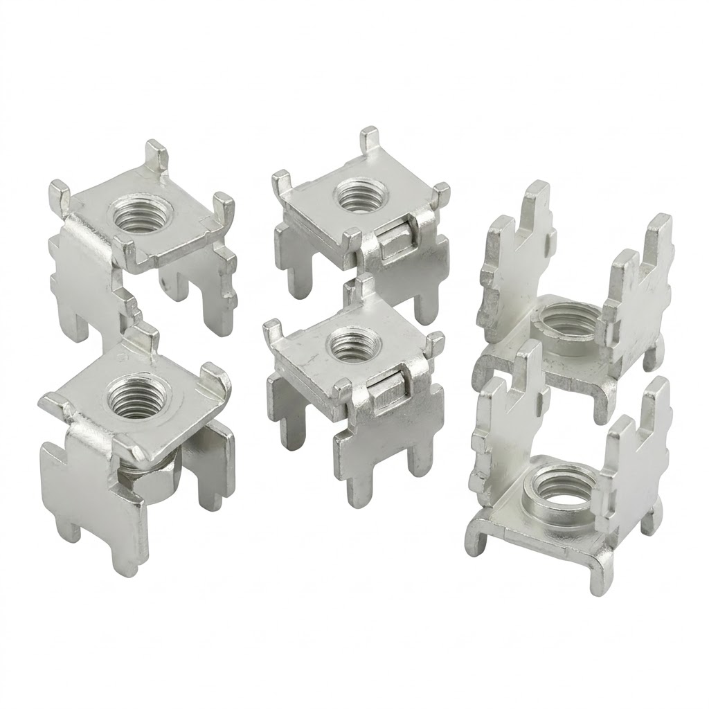
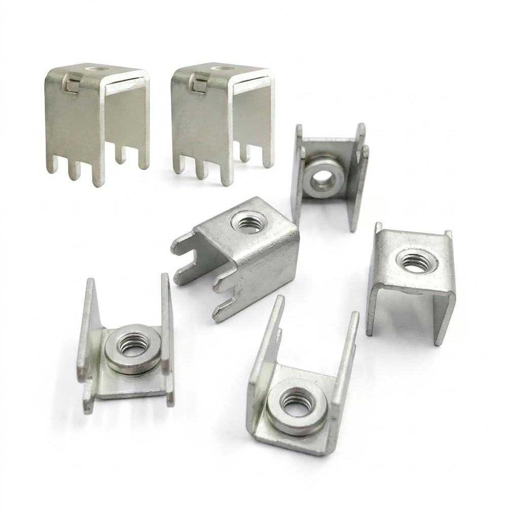
The TLS54103 Wire Screw Connector Terminal is one of their flagship screw-type terminals, engineered specifically for high-maintenance, high-vibration environments.
6.1 Core Specifications
| Parameter | Specification |
|---|---|
| Product Name | Terminal Connector |
| Model | TLS54103 |
| Rated Voltage | 600 V |
| Body Material | Copper / Brass |
| Surface Finishing | Silver / Nickel Plated |
| Origin | Guangdong, China |
| Certification | ISO certified |
6.2 Design Advantages for Serviceability
- Screw-type clamping mechanism: Unlike spring terminals that degrade with each insertion, the TLS54103 uses a high-torque screw clamp that maintains consistent pressure across 50+ disassembly cycles.
- Robust retention barb: The rear barb design provides strong holding force while allowing clean extraction when the screw is fully loosened.
- Superior plating adhesion: The silver/nickel plating passes a 48-hour salt spray test, meaning repeated handling does not cause premature corrosion.
- High vibration resistance: Ideal for automotive and industrial applications where mechanical shock would loosen lesser terminals.
6.3 Target Applications
- Battery systems & BMS
- Automotive wiring & power distribution
- Industrial power supplies & controls
- Cable connection assemblies
- Energy storage systems (BESS)
For detailed specifications, dimensional drawings, and customization options, visit the official product page:
👉 TLS54103 Wire Screw Connector Terminal
7. Expert Tips for Long-Term Terminal Reliability
To maximize terminal lifespan and minimize maintenance frequency, follow these data-validated best practices:
- Track disassembly cycles: Most screw terminals are rated for 50–100 assembly cycles. Exceeding this limit gradually degrades thread integrity and contact surface finish.
- Follow torque specifications: For M3 terminal screws, use 0.5–0.8 N·m torque; for M4, use 0.8–1.2 N·m. Under-torquing causes overheating; over-torquing strips threads.
- Schedule periodic resistance testing: Measure contact resistance every 6 months. A >20% increase indicates oxidation or loosening and requires immediate maintenance.
- Match plating to environment: In high-humidity or corrosive atmospheres, silver/nickel plated terminals (like TLS54103) have an 85% lower corrosion rate than standard tin-plated terminals.
- Keep OEM spare terminals on hand: Having original manufacturer terminals on hand reduces repair time by 60% and ensures mechanical and electrical compatibility.
Conclusion
Removing connector terminal pins may seem like a simple task, but small mistakes have large consequences for reliability, cost, and safety. By following data-driven procedures, using the right tools, and selecting terminals designed for maintainability, you can drastically reduce failure rates and extend the life of your electrical systems.
The TLS54103 from Telian combines robust construction, premium plating, and a screw-type design that stands up to repeated maintenance — making it an excellent choice for 600V industrial, automotive, and energy storage applications. With Telian’s in-house R&D, precision manufacturing, and automated assembly capabilities, you get consistent quality you can count on.
If you have questions about terminal selection, application engineering, or custom solutions, reach out to our team using the contact information below.
Contact Information
- Name: June
- Phone: +86 15855488151
- Email: lihelong@telian.cn
- Website: https://www.duanzitai.com/
The Indispensable Core Partner of Solar
Related Article