
How to Use Terminal Block Connectors
author: calrk
2026-04-10
How to Use Terminal Block Connectors: A Comprehensive 1000-Word Guide for Industrial & Commercial Applications
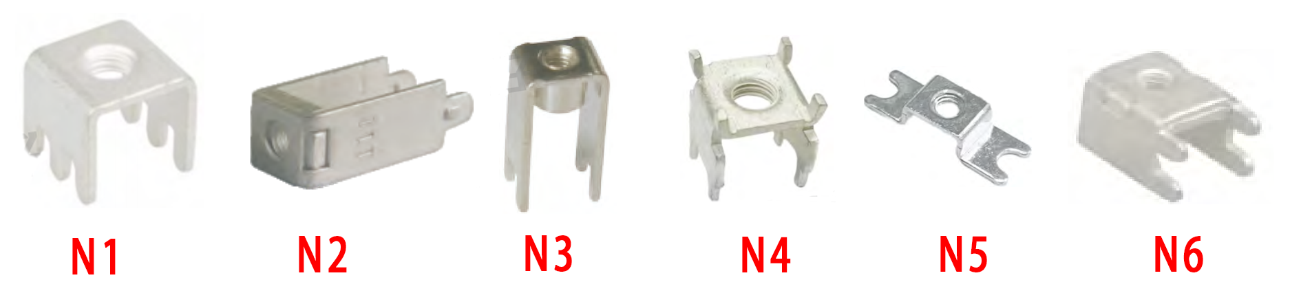
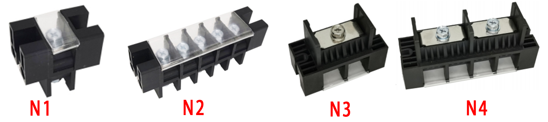
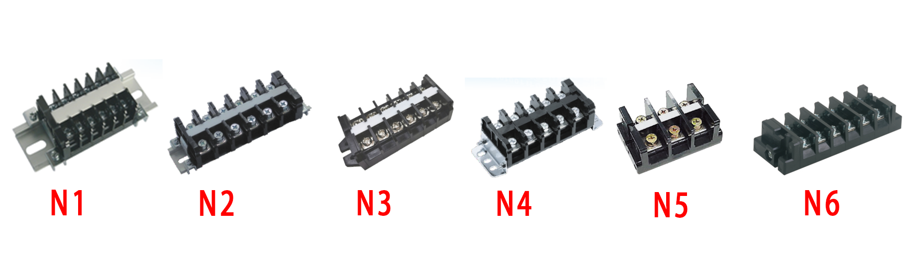
Terminal block connectors are indispensable components in electrical systems, serving as safe, organized interfaces for connecting wires, PCBs, and devices across industrial automation, renewable energy, smart homes, and power distribution. Using these connectors correctly is critical to ensuring circuit stability, preventing hazards like short circuits or overheating, and complying with international standards (IEC 60947-7-1, UL 1059). This guide details step-by-step procedures, safety protocols, tool requirements, and practical tips, covering both low-current signal wiring and high-power applications requiring copper lugs.
1. Pre-Use Safety Preparation & Preparation
1.1 Prioritize Electrical Safety
- Complete Power Disconnection: Turn off the main power supply and lock the switch to prevent accidental reactivation. Use a calibrated multimeter to verify zero voltage—for high-voltage systems (≥300V) or energy storage equipment, perform a secondary check with a voltage tester pen.
- Discharge Residual Electricity: Capacitor-equipped circuits (e.g., inverters, UPS systems) retain residual charge even after power-off. Use a dedicated discharge tool or short-circuit the capacitor terminals (with insulated gloves) to eliminate electric shock risks.
- Personal Protective Equipment (PPE): Wear insulated gloves (rated ≥1000V), safety goggles, and non-slip shoes. Avoid loose clothing or jewelry that could contact live components.
1.2 Verify Compatibility & Gather Tools
- Specifications Matching: Confirm the terminal block’s rated current (must ≥1.25× the circuit’s operating current) and voltage (≥1.5× the system voltage). Match the connector to the wire cross-section (common ranges: 0.14mm²–16mm² for standard terminals, 10mm²–70mm² for high-current models).
- Tool Preparation:
- Essential tools: Precision wire stripper (adjustable for 0.5mm²–16mm² wires), insulated screwdriver set (Phillips/slotted), torque wrench (4–12 N·m range for industrial use), and multimeter.
- Specialized tools: Hydraulic crimping tool (for copper lugs), heat gun (for insulation protection), and wire brush (for cleaning contacts).
1.3 Wire & Environment Preparation
- Wire Treatment: Inspect wires for damage, oxidation, or oil contamination. Use sandpaper to remove rust from copper conductors and wipe with isopropyl alcohol for clean contact.
- Environmental Check: Ensure the operating area is dry, well-lit, and free of dust or flammable materials. For outdoor or humid environments, confirm the terminal block has an IP65+ protection rating.
2. Step-by-Step Usage Procedures
2.1 Wire Preparation: Strip Insulation Correctly
- Use an adjustable wire stripper to remove the insulation layer—strip length should match the terminal’s clamping chamber (typically 5–8mm for standard terminals, 10–15mm for high-current models with copper lugs).
- For solid wires: Ensure the stripped end is straight and free of burrs. For stranded wires: Gently twist the strands to form a tight bundle, preventing loose filaments from causing short circuits.
- Avoid over-stripping (exposes excess copper) or under-stripping (insulation is pinched, increasing resistance).
2.2 Choose the Right Connection Method
Method A: Direct Wiring (Low-Current/Small Wires)
- Application: For 0.14mm²–6mm² solid or fine-stranded wires (signal lines, control circuits).
- Steps:
- Loosen the terminal screw counterclockwise 2–3 turns—do not fully remove the screw to avoid losing internal components.
- Insert the stripped wire straight into the terminal’s clamping chamber until it touches the bottom. Ensure no bare copper extends beyond the insulation housing.
- Tighten the screw clockwise with a torque wrench: Apply 0.2–0.6 N·m for small wires (≤2.5mm²) and 1–4 N·m for medium wires (4–6mm²). Avoid over-tightening (cracks the housing) or under-tightening (loose connections).
Method B: Copper Lug Wiring (High-Current/Large Wires)
- Application: Mandatory for 10mm²+ multi-strand wires, power cables, or industrial circuits (per IEC 60352-2).
- Steps:
- Select a copper lug matching the wire size (e.g., 16mm² wire → 16mm² OT-type lug). Crimp the lug onto the stripped wire using a hydraulic tool: Position the tool’s mold over the lug’s barrel, apply uniform pressure (≥8MPa for 16mm² wires) until the mold closes fully.
- Slide a heat-shrink tube over the crimped joint, covering the lug and 10mm of the wire’s insulation. Heat evenly with a heat gun until the tube adheres tightly (no bubbles).
- Insert the copper lug into the terminal block, ensuring its flat surface fully contacts the terminal’s conductive plate. Tighten the fixing screw with a torque wrench (8–12 N·m for 16–35mm² lugs).
2.3 Post-Installation Inspection
- Mechanical Check: Gently pull the wire to confirm it is firmly secured. For copper lug connections, verify no gaps exist between the lug and terminal.
- Electrical Testing: Use a multimeter to measure contact resistance—values ≤0.05mΩ indicate a good connection. Check for short circuits between adjacent terminals.
- Visual Inspection: Ensure no loose strands, exposed copper, or damaged insulation. Label wires with their function/position for future maintenance.
2.4 Power-On Validation
- Restore power gradually and monitor the terminal block for 15–30 minutes. Use an infrared thermometer to check for abnormal heating (temperature rise ≤30K under full load).
- For critical systems (e.g., energy storage, medical equipment), conduct a 24-hour stability test to confirm no voltage drops or connection failures.
3. Practical Tips & Common Mistakes to Avoid
3.1 Key Usage Tips
- Modular Terminal Assembly: For multi-position terminal blocks, use side-locking clips to connect modules securely. Add end caps and labeling strips for organization.
- Vibration-Proof Measures: In industrial machinery or automotive applications, choose anti-loosening terminals (with lock washers) and apply thread-locking adhesive to screws.
- Waterproof Protection: For outdoor use, seal terminal connections with waterproof tape or use IP67-rated connectors to resist rain, dust, and salt spray.
3.2 Common Errors & Solutions
- Mismatched Specifications: Using a 10A terminal for a 20A circuit causes overheating. Solution: Always select terminals with a current rating 25% higher than the circuit’s maximum load.
- Poor Crimping: Loose copper lugs lead to arcing. Solution: Use calibrated crimping tools and inspect lugs for full, crack-free deformation.
- Over-Stripping Wires: Exposed copper causes short circuits. Solution: Mark the stripper with the correct length for your terminal block.
- Reusing Damaged Terminals: Bent screws or worn springs reduce conductivity. Solution: Replace terminals with cracked housings, rusted contacts, or stripped threads.
4. Compliance & Maintenance
4.1 Adhere to International Standards
- Ensure terminal blocks meet IEC 60947-7-1 (mechanical/electrical requirements) and UL 94 V-0 (flame retardancy). For medical equipment, comply with ISO 13485; for automotive use, follow IATF 16949.
4.2 Routine Maintenance
- Inspect terminals quarterly for loose screws, corrosion, or overheating (discoloration of the housing).
- Clean dust and debris with a dry brush—avoid water or chemical cleaners.
- Replace terminals every 5–8 years (or sooner in harsh environments) to prevent aging-related failures.
5. Conclusion
Using terminal block connectors correctly requires a combination of safety awareness, precise operation, and compliance with standards. From low-current signal wiring to high-power industrial applications, following the steps outlined—prioritizing safety, matching specifications, using proper tools, and conducting thorough inspections—ensures reliable, long-lasting connections. Whether you’re installing terminals in a solar inverter, control cabinet, or smart home system, attention to detail minimizes hazards and maximizes system efficiency. For high-quality terminal blocks with robust performance and full compliance, partner with trusted manufacturers like Telian Electronic to meet the demands of diverse electrical projects.
What is a Terminal Block Used For
How to Remove DIN Rail Terminal Blocks
Related Article
In industrial electrical systems, battery storage, and automotive wiring, connector terminal pins are the unsung backbone of power and signal transmission.
how to remove connector terminal pins
olar and energy storage inverters are the core equipment of the new energy industry, responsible for converting DC power generated by photovoltaic panels and lithium battery packs into usable AC power.
The Indispensable Core Partner of Solar