
How to Remove DIN Rail Terminal Blocks
author: clark
2026-04-09
How to Remove DIN Rail Terminal Blocks – Standard Safe Procedure with Detailed Guidelines
DIN rail terminal blocks are widely used in industrial control cabinets, photovoltaic inverters, energy storage systems, power distribution units, and automation equipment due to their modular design and easy installation. However, removing them incorrectly can lead to damage to the terminal block itself, DIN rail deformation, wire breakage, or even safety hazards such as short circuits and electric shocks. Whether for maintenance, replacement, or system upgrades, following a standardized removal process is critical to ensuring operational safety and equipment integrity. This article expands on the core steps with detailed operating guidelines, tool specifications, common problem solutions, and safety norms, totaling over 1000 words to provide comprehensive technical support.
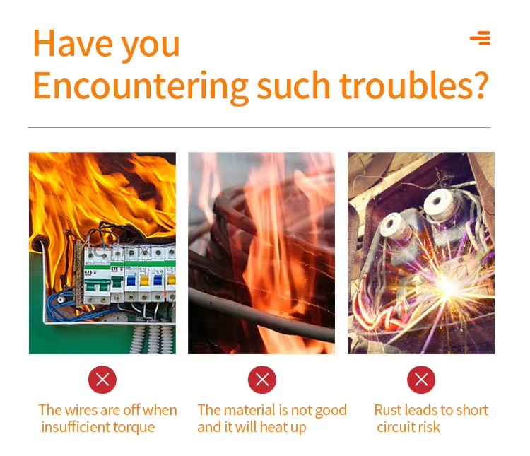
1. Pre-Removal Safety Preparation: Lay the Foundation for Safe Operation
Safety is the top priority when working with electrical components. Skipping any preparation step may result in irreversible damage or accidents.
1.1 Complete Power Disconnection & Verification
- First, turn off the main power switch of the equipment or control cabinet and lock it with a safety lock to prevent accidental power restoration by others.
- Use a calibrated multimeter (set to the AC/DC voltage range matching the system) to test the terminals and connected wires. Confirm that the voltage reading is zero; for high-voltage systems (above 300V), use a voltage tester pen for secondary verification.
- For energy storage systems or circuits with capacitors, discharge the residual electricity first. Disconnect the capacitor leads or use a dedicated discharge tool to ensure no residual voltage remains, as sudden discharge during disassembly can cause electric shocks.
1.2 Wire Labeling & Documentation
- Before disconnecting any wires, use waterproof labels to mark each wire’s function, terminal position, and corresponding connection point (e.g., “Inverter Output – Terminal 3L – PCB Port J12”). This avoids confusion during reinstallation and reduces debugging time.
- For complex systems with dozens of terminals, take photos or draw a wiring diagram to record the original layout. This is especially important for customized wiring or non-standard configurations.
1.3 Tool Preparation & Inspection
Prepare the following professional tools to ensure smooth removal:
- Small flat-head screwdriver (2–3mm blade width): Used to release the terminal’s locking latch; choose a high-quality tool with a rigid blade to avoid bending or breaking.
- Phillips screwdriver (size matching terminal screws): For loosening wire-clamping screws; magnetic tips help prevent screw loss.
- Torque wrench (optional but recommended for industrial scenarios): Used to loosen high-torque terminal screws (common torque range: 4–12 N·m) to avoid over-loosening or thread damage.
- Insulated gloves (rated voltage ≥ 1000V): Protects against residual electricity and prevents hand contact with sharp edges of terminals or rails.
- Wire cutters and wire strippers (backup): For handling damaged wires if necessary.
- Brush and lint-free cloth: To clean dust and debris from the DIN rail and terminal area after removal.
1.4 Environmental Preparation
- Ensure the operating area is well-lit and dry. Avoid working in humid or dusty environments, as moisture can cause short circuits, and dust may affect subsequent reinstallation.
- Clear the area around the DIN rail of tools, spare parts, or other obstacles to prevent accidental collisions during operation.
2. Disconnect All Wires: Avoid Damage to Conductors and Terminals
Before removing the terminal block from the DIN rail, all connected wires must be completely disconnected. This step requires patience and precision to avoid damaging the wire insulation or terminal’s internal clamping structure.
2.1 Wire Disconnection for Screw-Terminal Blocks
- Hold the screwdriver vertically and insert it into the screw slot of the terminal. Turn counterclockwise slowly to loosen the screw; stop when the clamping platform inside the terminal is fully raised (usually 2–3 full turns). Do not unscrew the screw completely, as this may cause the screw or internal clamping components to fall off and be lost.
- Gently pull the wire straight outward along the direction of the terminal’s wiring hole. For solid wires, pull with uniform force; for stranded wires, avoid twisting to prevent strand breakage. If the wire is tight, slightly adjust the screw’s tightness (loosen 1/4 turn) instead of pulling forcefully.
- For wires crimped with copper lugs (common in high-current circuits ≥10mm²), fully unscrew the terminal’s fastening screw until the copper lug can be smoothly removed. Inspect the copper lug for deformation; if damaged, mark it for replacement.
2.2 Wire Disconnection for Spring-Clamp Terminal Blocks
- Spring-clamp terminals (tool-free or tool-operated) require pressing the release lever or inserting a screwdriver into the release hole to unlock the spring mechanism.
- For tool-free terminals: Press the orange or gray release lever downward with your finger until you hear a “click” sound, then pull the wire out directly.
- For tool-operated terminals: Insert a flat-head screwdriver into the release hole and press inward to release the spring’s clamping force, then gently extract the wire.
2.3 Post-Disconnection Inspection
- After disconnecting all wires, check the terminal’s wiring holes for residual copper strands, insulation debris, or dust. Use a brush to clean them to prevent short circuits when the terminal is reused.
- Inspect the wire ends for damage: If the insulation layer is torn or copper strands are broken, trim the damaged part with wire cutters and re-strip the insulation (if the wire will be reused).
3. Release the DIN Rail Locking Mechanism: Correctly Detach the Terminal
DIN rail terminals (complying with DIN EN 50022 standard) use a spring-loaded plastic latch at the bottom to lock onto the top-hat DIN rail (common sizes: 35mm × 7.5mm or 35mm × 15mm). The key to removal is to properly release this latch without damaging it.
3.1 Single Terminal Removal
- Hold the terminal with one hand to stabilize it, and insert the flat-head screwdriver into the latch slot at the bottom of the terminal. The latch is usually located in the middle or at both ends of the terminal’s bottom; it is a small plastic tab that snaps onto the DIN rail.
- Gently pry the latch outward (toward the direction away from the rail) with the screwdriver. You will feel a slight “pop” as the latch disengages from the rail’s edge. Do not use excessive force, as the plastic latch is brittle and prone to breaking.
- While keeping the latch in the released position, slide the terminal horizontally along the DIN rail (either left or right) by 2–3mm. This separates the terminal’s bottom hook from the rail, allowing it to be lifted directly upward and removed.
3.2 Removal of Modular Terminal Groups
Most DIN rail terminals are assembled into modular groups using side locking clips or interlocking mechanisms for unified wiring and management. Removing such groups requires additional steps:
- First, remove any jumpers, busbars, or cross-connecting bars between the terminals. These components are usually fixed with small screws or snap-on designs; loosen the screws or gently pry the snap clips to disconnect them.
- Remove the end caps or partition plates at both ends of the terminal group. These parts prevent dust entry and protect the side locks; they can be pulled off directly or pried open with a screwdriver.
- Release the side locking clips between adjacent terminals. Each terminal has a small plastic clip on the side that connects to the next one; insert a screwdriver into the clip’s gap and gently pry to separate them.
- Remove the terminals one by one starting from either end of the group. Do not pull the entire terminal group forcefully, as this may cause multiple latches to break or the DIN rail to bend.
3.3 Handling Special Terminal Designs
- For high-current terminal blocks (rated current ≥100A) or heavy-duty models, additional fixing screws may be installed on the terminal to enhance stability. Before releasing the latch, use a screwdriver to remove these fixing screws.
- Some waterproof or anti-vibration terminals are equipped with metal clips that wrap around the DIN rail. Use pliers to gently squeeze the clips to release them before prying the plastic latch.
4. Post-Removal Inspection & Handling: Ensure Reusability and Safety
After removing the terminal block, proper inspection and handling are essential to ensure it can be reused or disposed of safely.
4.1 Inspection of Terminal Blocks
- Check the plastic housing for cracks, deformation, or damage to the latch. If the latch is broken, the terminal cannot be securely fixed to the DIN rail and should be replaced.
- Inspect the internal clamping components (screws, spring clips, conductive plates) for rust, deformation, or loose parts. For screw terminals, ensure the screw can rotate smoothly without jamming; for spring terminals, verify that the spring rebounds elastically.
- Test the terminal’s conductivity with a multimeter if it will be reused. Connect the multimeter probes to the terminal’s two wiring holes; the resistance should be close to zero, indicating good conductivity.
4.2 Inspection of DIN Rail
- Check the DIN rail for bending, deformation, or corrosion. If the rail is bent, use a rail straightener to correct it (ensure the straightness tolerance is within ±0.5mm/m) to avoid affecting the installation of new terminals.
- Clean the rail surface with a lint-free cloth dipped in isopropyl alcohol to remove dust, oil, or oxidation, which ensures a tight fit between the terminal latch and the rail.
4.3 Storage of Terminal Blocks
- For reusable terminals, sort them by type, current rating, and number of positions, and store them in a dry, dust-free toolbox. Place a piece of foam or soft cloth at the bottom of the box to prevent scratches on the plastic housing.
- Keep screws, jumpers, end caps, and other accessories with the corresponding terminals. Use small sealed bags to package small parts to avoid loss.
- For damaged terminals, dispose of them in accordance with electronic waste recycling regulations. Separate plastic housings and metal components if possible to facilitate environmental protection recycling.
5. Common Problems & Solutions During Removal
5.1 Latch is Stuck and Cannot Be Released
- Cause: Long-term use in high-temperature or high-humidity environments causes plastic aging and adhesion, or dust accumulation in the latch slot.
- Solution: Use a brush to clean the latch slot with compressed air, then apply a small amount of silicone lubricant (avoid oil-based lubricants that attract dust). Gently tap the terminal with a rubber hammer to loosen the latch before prying.
5.2 Terminal is Deformed and Cannot Be Slid
- Cause: Over-tightening during installation or external impact causes the terminal’s bottom hook to deform.
- Solution: Use pliers (wrapped with a soft cloth to avoid scratching) to gently adjust the deformed hook back to its original shape. If deformation is severe, replace the terminal to prevent unstable installation later.
5.3 Screw is Seized and Cannot Be Loosened
- Cause: Thread rust or over-tightening during installation.
- Solution: Apply a small amount of rust remover (such as WD-40) to the screw and let it sit for 5–10 minutes. Use a torque wrench to apply steady force counterclockwise; do not use excessive force to avoid breaking the screw.
5.4 DIN Rail Bends During Removal
- Cause: Pulling the terminal group forcefully or uneven force when prying the latch.
- Solution: Stop the operation immediately and use a DIN rail straightener to correct the bend. For severely bent rails, replace them entirely, as deformation may affect the stability of all subsequent terminal installations.
6. Safety Norms & International Standards Compliance
- Compliance with IEC 60947-7-1: This international standard specifies the mechanical and electrical requirements for DIN rail terminal blocks. During removal, ensure that the terminal’s structural integrity is not damaged, and the DIN rail’s dimensional accuracy is maintained.
- Prohibition of Live Operation: According to OSHA (Occupational Safety and Health Administration) regulations, electrical work must be performed under “zero-energy” conditions. Live removal of terminals is strictly prohibited, and violations may result in severe safety accidents.
- Personal Protection: Wear insulated gloves, safety goggles, and non-slip shoes during operation. Avoid wearing loose clothing or jewelry that may come into contact with electrical components.
7. Conclusion
Removing DIN rail terminal blocks is a seemingly simple task, but it requires strict adherence to safety procedures, precise operation, and careful inspection. From complete power disconnection and wire labeling to correct latch release and post-removal maintenance, each step is crucial to ensuring the safety of personnel and the integrity of equipment. By following the detailed guidelines in this article, engineers, maintenance technicians, and installation teams can effectively avoid common mistakes, reduce equipment damage, and improve work efficiency.
For high-quality DIN rail terminal blocks with reliable locking mechanisms, strong durability, and easy removal, choosing a trusted supplier like Telian Electronic ensures long-term operational stability. If you encounter special terminal types or complex removal scenarios, feel free to contact our technical support team for customized solutions.
How to Use Terminal Block Connectors
What Does the Terminal Block Do
Related Article
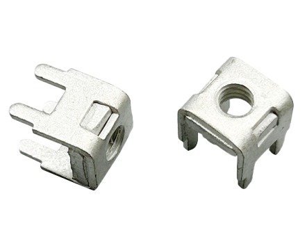
In industrial electrical systems, battery storage, and automotive wiring, connector terminal pins are the unsung backbone of power and signal transmission.
how to remove connector terminal pins
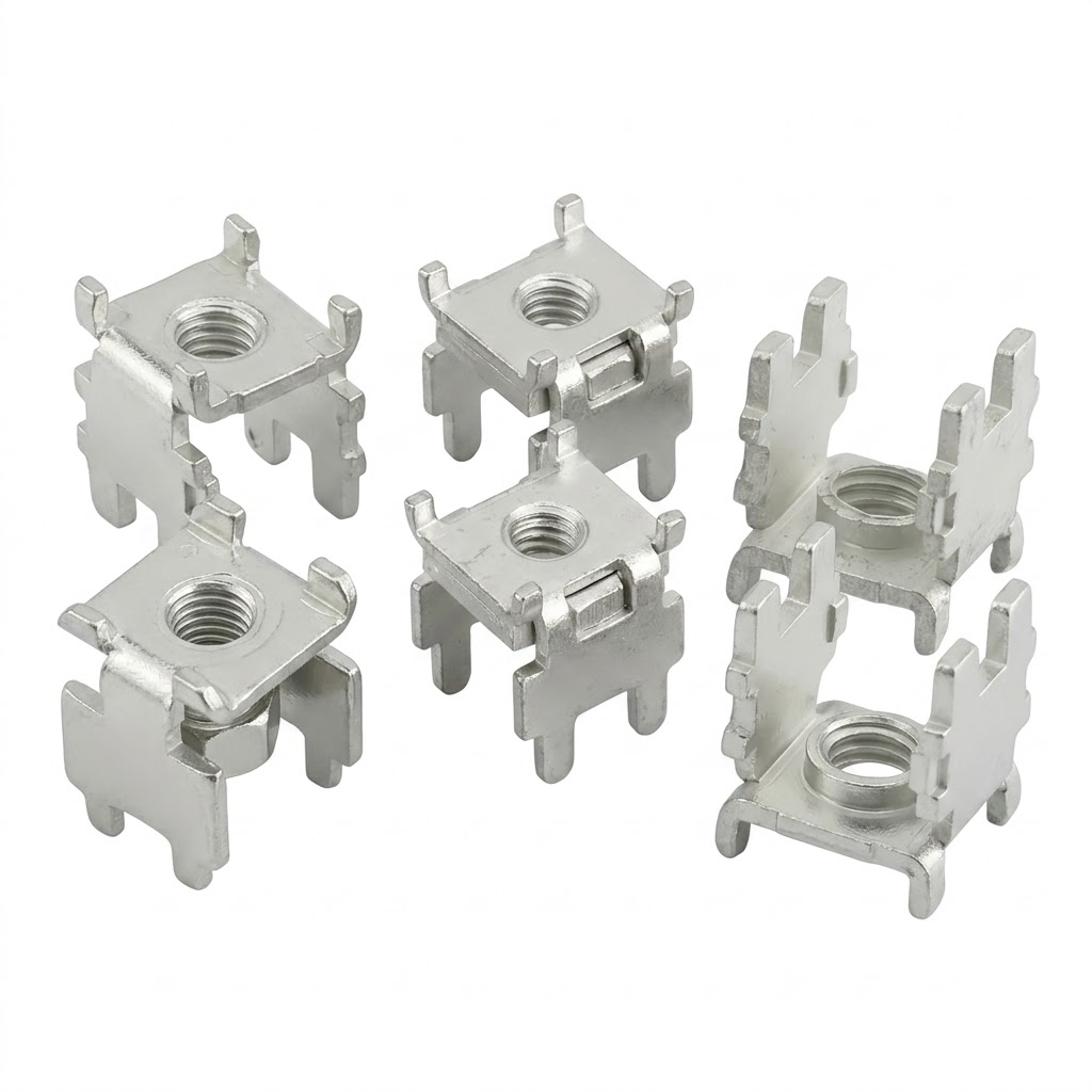
olar and energy storage inverters are the core equipment of the new energy industry, responsible for converting DC power generated by photovoltaic panels and lithium battery packs into usable AC power.
The Indispensable Core Partner of Solar