
Why Use PCB Terminal Block on BMS
author: clark
2026-05-07
Why Use PCB Terminal Block on BMS? Critical Roles in Battery Management Systems & Inverters
Published on: 2026-05-07 | Author: Telian Electronics | Source: duanzitai.com
Introduction
In the rapidly evolving landscape of energy storage and electric vehicles, Battery Management Systems (BMS) and inverters stand as the backbone of reliable, efficient energy conversion and storage. These critical components demand connections that are not only electrically stable but also mechanically robust, thermally resilient, and easily maintainable. This is where PCB terminal blocks—especially PCB screw terminals—prove indispensable.
This comprehensive guide will explain why PCB terminal blocks are essential for BMS and inverters, the key differences between SMD and DIP mounting technologies, and how Telian Electronics—a leading manufacturer with over 1,000 PCB screw terminal models—delivers the ideal connection solutions for these high-stakes applications.
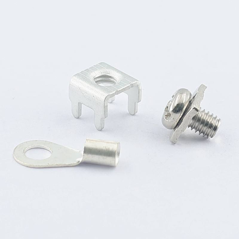
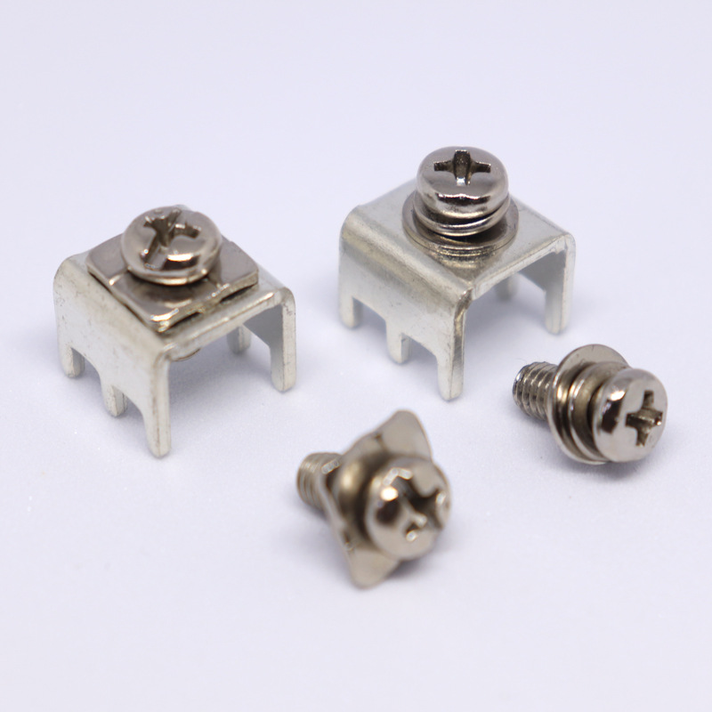
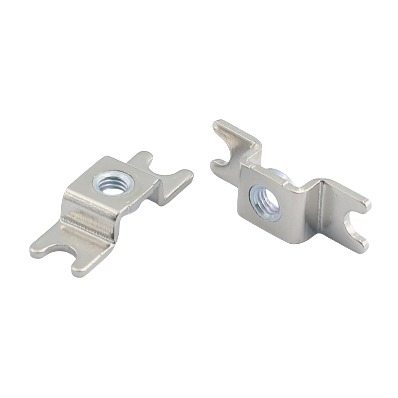
1. The Critical Role of PCB Terminal Blocks in BMS
1.1 What is a BMS and Why Connection Matters
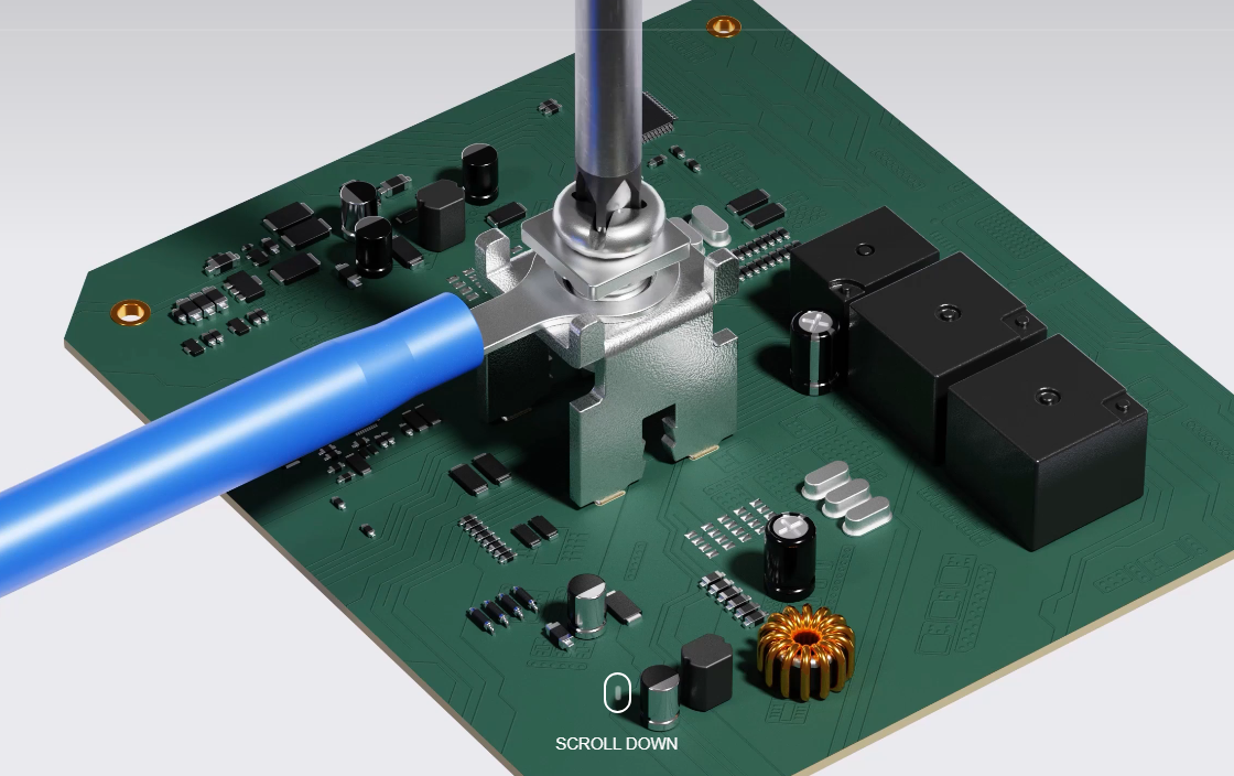
A Battery Management System (BMS) is the "brain" of any lithium-ion battery pack, responsible for monitoring cell voltages, temperatures, and currents while ensuring safe operation through protection mechanisms like overcharge, over-discharge, and short-circuit prevention. In high-power applications such as electric vehicles, grid storage, and industrial UPS systems, BMS must handle high currents (up to hundreds of amps) and high voltages (up to 1,500V) while maintaining precision measurement and control.
The reliability of BMS connections directly impacts:
- Safety: Preventing thermal runaway and electrical hazards
- Performance: Ensuring accurate cell balancing and efficient energy transfer
- Longevity: Minimizing resistance-induced heat and connection degradation
- Maintainability: Facilitating diagnostics and repairs without damaging the PCB
1.2 Why PCB Terminal Blocks are Superior to Direct Soldering
Traditional soldering of wires to PCBs creates permanent connections that suffer from several critical limitations in BMS applications:
| Limitation | PCB Terminal Block Solution |
|---|---|
| Thermal Stress | Solder joints crack under repeated heating/cooling cycles; terminal blocks isolate wires from PCB thermal expansion |
| Vibration Sensitivity | Solder connections fail in high-vibration environments (e.g., EVs); screw terminals maintain secure contact |
| High-Current Handling | Soldered wires have limited current capacity; terminal blocks use large contact areas and heavy-gauge conductors |
| Serviceability | Soldered wires require desoldering for repairs; terminal blocks allow tool-free disconnection/reconnection |
| Scalability | Soldering limits design flexibility; terminal blocks support modular system expansion |
1.3 Key Functions of PCB Screw Terminals in BMS
-
Cell Voltage MonitoringPCB screw terminals provide secure connections for voltage sense wires that monitor individual cell voltages, enabling precise cell balancing and state-of-charge (SOC) calculation.
-
Temperature SensingTerminals connect thermistor wires to the BMS, ensuring accurate temperature monitoring across all cells to prevent thermal runaway.
-
High-Current Power DistributionHeavy-duty PCB screw terminals handle the main power connections between the battery pack, BMS, and external load/inverter, with current ratings up to 100A+ depending on the model.
-
Communication InterfacesTerminals provide reliable connections for CAN bus, RS485, or Ethernet communication between the BMS, inverter, and other system components.
-
Balancing CircuitryScrew terminals connect cell balancing resistors or active balancing modules, ensuring all cells charge/discharge uniformly to maximize battery life.
2. PCB Terminal Blocks in Inverters: Power Conversion Made Reliable
2.1 Inverter Connection Challenges
Inverters convert DC power from batteries to AC power for grid or load use, operating under extreme electrical and thermal stress. They require connections that:
- Handle high-frequency switching currents (tens of kHz)
- Withstand high voltage spikes (up to 2-3x nominal voltage)
- Maintain low contact resistance to minimize power loss
- Provide isolation between high-power and control circuits
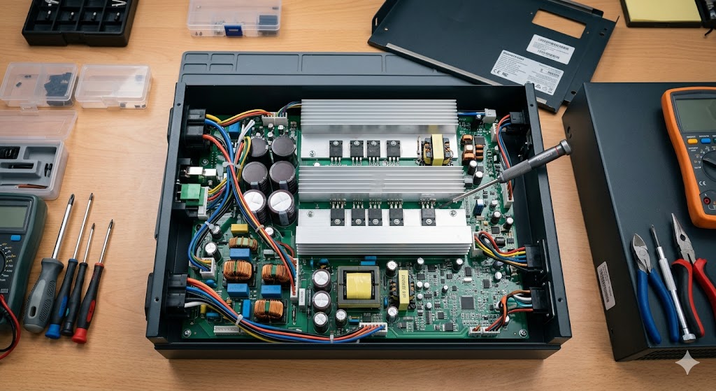
2.2 How PCB Screw Terminals Address Inverter Needs
-
DC Input ConnectionsHeavy-gauge PCB screw terminals connect the battery pack to the inverter's DC bus capacitors, handling hundreds of amps during peak power transfer.
-
AC Output TerminalsScrew terminals provide a safe, reliable interface for connecting the inverter's AC output to the electrical grid or loads, with proper insulation and creepage distances.
2.3 The Critical Need for Reliability in Inverters
Inverters operate in harsh environments with temperature swings, vibration, and electrical noise. PCB screw terminals provide:
- Gas-tight connections that prevent oxidation and maintain low resistance over time
- Mechanical stability that resists vibration-induced loosening
- Easy replacement of components without damaging the PCB
- Clear labeling for quick identification of critical connections
3. SMD vs. DIP PCB Terminal Blocks: Choosing the Right Technology
PCB terminal blocks are available in two primary mounting technologies, each optimized for specific applications and manufacturing requirements.
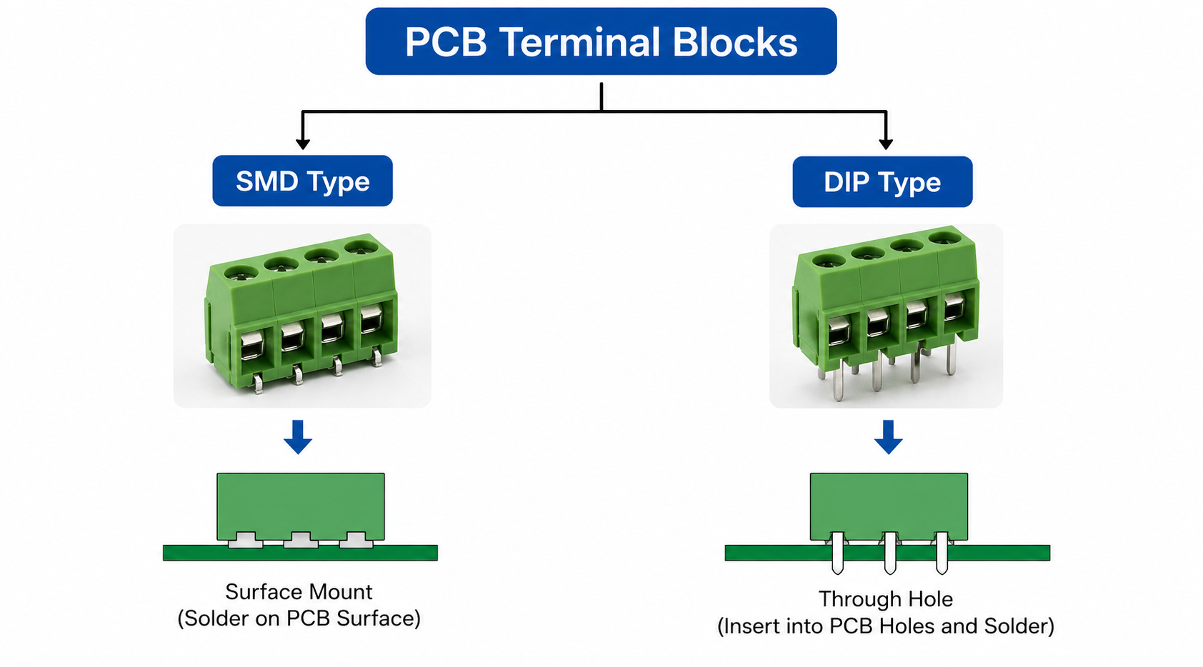
3.1 DIP (Through-Hole) PCB Terminal Blocks: The Rock-Solid Choice
DIP (Dual In-line Package) terminal blocks feature long pins that pass through pre-drilled holes in the PCB and are soldered on the opposite side, typically via wave soldering.
Key Advantages for BMS and Inverters:
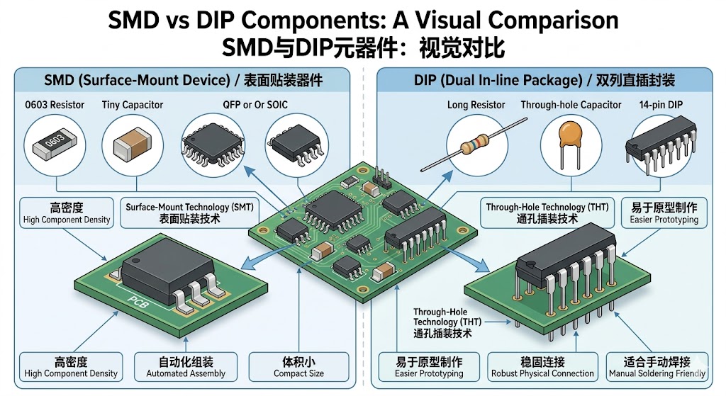
- Unmatched mechanical strength: DIP terminals anchor deeply into the PCB like "roots in soil," providing up to 50% greater resistance to vibration and pull-out forces compared to SMD equivalents
- Superior high-current handling: Through-hole design allows for larger cross-sectional area conductors and better heat dissipation, ideal for 50A+ applications
- Enhanced durability: Better able to withstand thermal cycling and physical stress in harsh industrial and automotive environments
- Easier field service: DIP terminals can be replaced with basic tools, critical for maintenance in remote locations
Best Applications:
- High-power BMS (100A+ current)
- Industrial inverters and grid-tie systems
- EV traction battery management
- Applications with significant vibration or mechanical stress
3.2 SMD (Surface Mount Device) PCB Terminal Blocks: Speed and Miniaturization
SMD terminal blocks are mounted directly onto the PCB surface pads and soldered via reflow soldering, compatible with fully automated SMT production lines.
Key Advantages for BMS and Inverters:
- Blazing-fast assembly: SMD components enable high-speed, automated production with placement rates up to 100,000 components per hour
- Space optimization: Compact design saves up to 30% PCB space, critical for miniaturized BMS and inverters
- Low parasitic inductance: Short terminal paths reduce electromagnetic interference (EMI) in high-frequency switching circuits
- Cost efficiency: Automated assembly reduces labor costs for high-volume production
Best Applications:
- Low-to-medium power BMS (up to 50A)
- Portable energy storage systems
- Consumer electronics and small inverters
- High-volume production runs requiring rapid assembly
3.3 Choosing Between SMD and DIP for Your BMS/Inverter
| Factor | SMD Terminal Blocks | DIP Terminal Blocks |
|---|---|---|
| Current Handling | Up to 50A (specialized models up to 76A) | 50A to 200A+ |
| Mechanical Strength | Medium (vibration-sensitive) | High (vibration-resistant) |
| Production Speed | Very high (fully automated) | Lower (manual or semi-automated) |
| PCB Space | Compact (ideal for miniaturization) | Larger footprint |
| Serviceability | Requires specialized tools | Easy to replace manually |
| Cost | Lower for high-volume production | Lower for low-volume and prototyping |
4. Telian Electronics: Your Trusted Partner for BMS & Inverter PCB Terminal Blocks
4.1 Why Telian's PCB Screw Terminals Excel in BMS & Inverters
- Optimized for high current: Heavy-duty copper alloy contacts minimize resistance and heat generation
- Vibration-resistant design: Screw clamping mechanism maintains contact integrity in high-vibration environments
- Thermal stability: High-grade PA66 or PPO insulation materials withstand extreme temperatures
- Safety features: Adequate creepage and clearance distances prevent arcing in high-voltage applications
- Easy installation: Tool-assisted wiring requires no specialized crimping tools
- Cost-effective: Competitive pricing without compromising quality, ideal for mass production
5. How to Select the Right PCB Terminal Block for Your BMS/Inverter
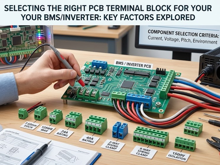
Follow this step-by-step guide to choose the optimal terminal block:
5.1 Step 1: Determine Current and Voltage Requirements
- Calculate maximum continuous current and peak current
- Identify system voltage (e.g., 48V, 400V, 800V)
- Select a terminal block with at least 125% of the calculated current rating for safety margin
5.2 Step 2: Choose Mounting Technology (SMD vs. DIP)
- DIP for high-current, high-vibration, or service-intensive applications
- SMD for compact designs, automated production, or low-to-medium current requirements
5.3 Step 3: Select Wiring Method
- Screw terminals for maximum reliability, vibration resistance, and reusability (best for BMS/inverters)
- Spring terminals for faster wiring in low-vibration environments
- Push-in terminals for tool-free, high-speed assembly
5.4 Step 4: Consider Environmental Factors
- Temperature: Choose terminals rated for -40°C to 125°C (or higher for harsh environments)
- Vibration: Select DIP terminals with reinforced mounting for automotive/industrial applications
- IP rating: Consider sealed terminals for outdoor or wet environments
5.5 Step 5: Verify Compatibility
- Ensure terminal block pitch matches PCB layout
- Confirm wire diameter compatibility (0.5mm² to 16mm² for most BMS/inverter applications)
- Check soldering compatibility with your PCB assembly process (reflow for SMD, wave for DIP
6. Conclusion: PCB Terminal Blocks – The Unsung Heroes of BMS & Inverter Reliability
PCB terminal blocks—especially PCB screw terminals—are far more than simple connectors; they are critical components that determine the safety, performance, and longevity of BMS and inverter systems. By providing secure, detachable connections that handle high currents, resist vibration, and simplify maintenance, they solve the most pressing connection challenges in energy storage and conversion applications.
The choice between SMD and DIP technologies depends on your specific requirements: DIP offers unmatched mechanical strength for high-power, high-vibration applications, while SMD enables rapid, automated production for compact designs.
As a leading manufacturer with over 1,000 PCB screw terminal models, Telian Electronics (duanzitai.com) combines technical expertise, extensive product range, and customization capabilities to deliver the ideal connection solutions for BMS and inverters. Whether you need standard components or specialized designs, Telian provides reliable, high-quality terminals that meet the rigorous demands of modern energy systems.
Investing in premium PCB terminal blocks from Telian is not just a component choice—it's a strategic decision to ensure your BMS and inverter systems operate safely, efficiently, and reliably for years to come.
How to Use Terminal Block Connector for Industrial Energy Storage
What Is a PCB Terminal Block A Complete Guide
Related Article
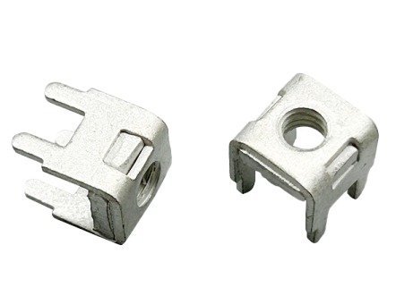
In industrial electrical systems, battery storage, and automotive wiring, connector terminal pins are the unsung backbone of power and signal transmission.
how to remove connector terminal pins
olar and energy storage inverters are the core equipment of the new energy industry, responsible for converting DC power generated by photovoltaic panels and lithium battery packs into usable AC power.
The Indispensable Core Partner of Solar